



Cementing Manifold Valve Assembly
Product Overview
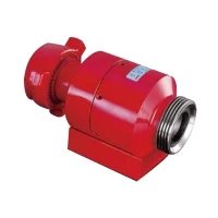
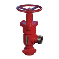
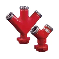
The Cementing Manifold Valve Assembly controls high-pressure slurry flow during oil and gas well cementing operations. Installed on cementing trucks or skid-mounted manifold trailers, it directs slurry under extreme pressures between pumps, mix tanks, and wellheads. Each assembly integrates heavy-duty valves, high-pressure piping segments, and reliable unions engineered to withstand abrasive fluid dynamics, pressure spikes, and corrosive wellbore environments.
Key Features
Reliable Seal Integrity: Metal-to-metal and elastomer secondary seals prevent slurry leakage during high-frequency pressure cycling.
Low Operating Torque: Streamlined internal flow paths minimize fluid turbulence and allow manual or hydraulic actuation under full rated pressure.
Streamlined Field Maintenance: Modular layout allows inline replacement of valve plugs, seats, and seals without removing the entire manifold header, reducing rig downtime.
In-House Manufacturing Integration: Forged bodies are machined on multi-axis CNC centers and assembled with strict dimensional tracking to ensure drop-in replacement capability.
Technical Specifications
|
Parameter |
Specification Range |
|
Working Pressure |
5,000 PSI to 15,000 PSI |
|
Nominal Size |
2 inch, 3 inch, 4 inch |
|
Temperature Rating |
-29°C to 121°C (Standard & H₂S Service) |
|
End Connections |
Fig 1502 Hammer Union (Male/Female), API Flanged, or Butt-Weld |
|
Material Grade |
AISI 4130 / 8630 Forged Alloy Steel |
|
Design Standard |
API Spec 6A / API Spec 16C compliant |
Applications
Primary & Remedial Cementing
Slurry distribution manifold on cementing pump units.
Frac & Well Service Support
High-pressure fluid routing during stimulation and pressure testing.
Drilling Rig Fluid Systems
High-pressure standpipe and mud manifold integrations.
Materials & Configuration
Valve Body: Drop-forged from high-strength AISI 4130 alloy steel with controlled sulfur content for optimal sour service resistance (NACE MR0175).
Internal Trim: Nitrided or tungsten-carbide coated plugs and seats to resist abrasive wear from cement slurries containing heavy sand, barite, or additives.
Seals: HNBR or Viton energizers combined with PEEK backup rings to prevent extrusion at 15,000 PSI.
Configuration Options: Available as plug valves, gate valves, or adjustable choke valves integrated into 3-way, 4-way, or custom multi-valve manifold blocks.
Quality Control & Manufacturing Process
Manufacturing Baseline: Backed by our in-house 5-axis CNC machining centers and API 6A licensed facility, ensuring precise geometric control from raw forging to final assembly.
Material Traceability: Raw forgings verified via positive material identification (PMI) and ultrasonic testing (UT) per ASTM standards before machining.
Machining Precision: CNC boring and turning centers maintain tight dimensional tolerances on critical seating surfaces to eliminate leakage paths.
Pressure Testing: Every assembly undergoes hydrostatic shell testing (1.5x working pressure) and high-pressure gas/hydraulic seat testing per API 6A guidelines prior to shipment.
Third-Party Verification: Full support for independent factory acceptance testing (FAT) witnessed by third-party inspection agencies (e.g., SGS, BV, DNV) upon request.
Surface Treatment: Phosphate coating or epoxy primer with marine-grade topcoat applied to withstand harsh offshore and desert rig environments.
Customization & OEM
Dimensional Matching
Reverse-engineered or custom-built to match existing OEM skid mounting footprints and major global brands (Halliburton, Schlumberger, SPM, Cameron).
Port Configurations
Tailored inlet/outlet configurations, custom union thread types (Fig 602, 1002, 1502), and specific flange drillings (ANSI / API).
Actuation Options
Manual handwheel, pneumatic, or hydraulic actuator mounts configured to rig automation requirements.
Packaging & Shipping
Protection: Flange faces and union threads fitted with heavy-duty steel or high-impact plastic protectors, sealed with anti-corrosion grease.
Crate Construction: Export-grade fumigated wooden crates or steel skids secured with internal bracing to prevent transit damage during ocean or air freight.
Documentation: Accompanied by Material Test Reports (MTRs / 3.1 certificates), pressure test charts, and API compliance certificates.
FAQ
Q: Are these valve assemblies fully interchangeable with standard 15,000 PSI cementing units and major brands like SPM or Cameron?
A: Yes. Dimensions, thread profiles (Fig 1502), and face-to-face lengths are engineered to match global oilfield standards for direct, drop-in replacement.
Q: What materials are used for sour gas (H₂S) operating conditions?
A: Bodies and internal trims are manufactured from specially heat-treated AISI 4130/4140 steel fully compliant with NACE MR0175 / ISO 15156.
Q: Can individual internal components (plugs and segments) be replaced in the field?
A: Yes. The modular plug valve design permits quick replacement of internal wear parts using standard field hand tools.
Q: What is the standard lead time for custom manifold configurations?
A: Standard configurations ship within 3 to 4 weeks. Custom engineered layouts require 6 to 8 weeks depending on forging availability.
Q: Do you accommodate third-party pre-shipment inspections?
A: Yes. We regularly cooperate with agencies like SGS, BV, and DNV for client-mandated Factory Acceptance Testing (FAT) and material verification.
Q: How do you protect threaded connections during ocean freight?
A: Threads and sealing surfaces are coated with anti-corrosion grease and sealed with heavy-duty thread protectors before crating.
Request a Quote
To receive a prompt technical proposal and quotation, please provide the following details:
Working Pressure: (e.g., 10,000 PSI or 15,000 PSI)
Nominal Size & Configuration: (e.g., 3-inch 3-valve manifold block)
End Connections: (e.g., Fig 1502 Female Union x Male Union)
Service Environment: (Standard service or Sour Service / NACE MR0175)
Quantity & Target Delivery Date
Drawings or OEM Part Numbers: (If matching an existing skid unit)
Hot Tags: cementing manifold valve assembly, China cementing manifold valve assembly suppliers, factory
Previous
No InformationYou Might Also Like


Send Inquiry