

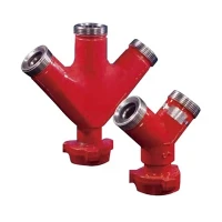


Cementing Suction Manifold
Product Overview
The Cementing Suction Manifold manages fluid intake distribution between mixing tanks, boost pumps, and high-pressure cementing triplex or quintuplex pumps. Built for heavy-duty oilfield service, it coordinates slurry suction, fluid transfer, and system flushing while withstanding abrasive wear and corrosive downhole chemical additives. Engineered for rapid rig-up on cementing trailers and skid units, the manifold integrates high-integrity valves, thick-walled piping runs, and standardized connection ports to maintain steady suction head pressure and prevent pump cavitation.
Key Features
Erosion-Resistant Flow Paths: Internal fluid pathways feature sweeping bend radiuses and thick-walled forged blocks that minimize fluid turbulence and combat abrasive wear from cement slurries containing heavy weighting agents (barite, hematite).
Reliable Isolation Control: Equipped with heavy-duty mud valves or plug valves ensuring positive shut-off and quick switching between suction sources (mix water, slurry, recirculation).
Vibration Dampening Design: Rigid structural skid mounting and reinforced gusseted support brackets isolate flow-induced vibration, protecting pipe joints and welded connections during continuous high-rate pumping.
Simplified Maintenance: Flanged and union-connected modular sub-assemblies allow rapid field inspection, seal replacement, and valve servicing without cutting or re-welding piping runs.
Technical Specifications
|
Parameter |
Specification Range / Standard |
|
Working Pressure |
5,000 PSI to 10,000 PSI (Custom ratings up to 15,000 PSI available) |
|
Nominal Pipe Size (NPS) |
2 in, 3 in, 4 in, 6 in |
|
Material Grade |
Forged Alloy Steel (AISI 4130 / 8630) |
|
Sour Service Compliance |
NACE MR0175 / ISO 15156 available |
|
Inlet / Outlet Connections |
Fig 602, Fig 1002, Fig 1502 Hammer Unions, API Flanges |
|
Valve Type |
Integral Plug Valves, Gate Valves, Check Valves |
|
Operating Temperature |
(-29^\circ\text{C}) to (121^\circ\text{C}) (Standard), (-46^\circ\text{C}) (Low-temp optional) |
|
Manufacturing Standards |
API Spec 6A, API Spec 16C, ASME Section VIII |
Applications
Primary & Remedial Cementing
Integrated into twin-pump cementing trucks and skid packages to supply consistent fluid feeds during casing and liner cementing operations.
Fluid Batch Mixing & Transfer
Connects bulk mixing tanks to displacement pumps during high-volume slurry preparation.
Offshore & Onshore Drilling Rigs
Functions as a centralized fluid distribution node on mobile well-service spreads.
Materials & Configuration
Body Construction: Manufactured from forged alloy steel blocks or seamless heavy-wall mechanical tubing (ASTM A519 / AISI 4130), eliminating internal casting defects and ensuring structural integrity under surge pressures.
Manifold Layout: Configurable in single-header, dual-header, or loop configurations with bypass lines, bleed valves, and pressure gauge ports.
Sealing System: Utilizes HNBR or Viton elastomeric seals paired with metal-to-metal backup seals to prevent leakage under pressure surges and exposure to aggressive chemical additives.
Surface Protection: External surfaces are blast-cleaned to Sa 2.5, coated with corrosion-resistant marine epoxy primer, and finished with oilfield-grade polyurethane enamel.
Manufacturing & Quality Control
Our manufacturing facility utilizes advanced CNC vertical machining centers and automated orbital welding systems operated by certified welders (AWS D1.1 / ASME Section IX) to ensure dimensional precision and weld integrity.
Material Traceability: 100% material test reports (MTRs) provided from raw ingot to finished forged component.
Non-Destructive Examination (NDE): All critical weldments and high-stress stress zones undergo 100% Magnetic Particle Testing (MT) or Ultrasonic Testing (UT).
Hydrostatic Pressure Testing: Every manifold is factory pressure-tested to 1.5 times its rated working pressure using certified test rigs, holding test pressure for a minimum duration per API specifications.
Dimensional Inspection: Coordinate Measuring Machines (CMM) and laser trackers verify bolt-hole patterns, flange face parallelism, and skid mounting footprint accuracy.
Customization & OEM
Footprint Matching
Piping dimensions, centerline heights, and lifting lug locations can be engineered to match existing truck chassis or skid frames.
Port Customization
Integration of specific union types (WECO, Chiksan) or proprietary flange standards per rig specifications.
Instrumentation Integration
Provision for inline flow meters, pressure transducers, and automated pneumatic or hydraulic valve actuators.
Packaging & Shipping
Protection: All threaded connections, hammer union threads, and flange faces are fitted with heavy-duty plastic thread protectors and steel blanking covers.
Crate Build: Secured onto custom heavy-duty wooden skids with bolted retention brackets, wrapped in VCI (Volatile Corrosion Inhibitor) plastic film to prevent moisture damage during ocean transit.
Documentation Pack: Each shipment includes a complete quality dossier: MTRs, hydrostatic test charts, NDE reports, and operation/maintenance manuals.
Frequently Asked Questions
Q: Are the manifold materials certified for sour gas (H2S) service?
A: Yes. When specified, we use AISI 4130/8630 forged steel processed with specific heat treatments to meet NACE MR0175 / ISO 15156 hardness limits, supplied with full metallurgical test documentation.
Q: What hammer union standards are used on the inlet/outlet ports?
A: Standard configurations use API-compatible Fig 602, Fig 1002, or Fig 1502 unions. Custom thread forms or Grayloc/ANSI flanged connections can be supplied upon request.
Q: How do you prevent internal erosion from abrasive cement slurries?
A: Flow-turning areas use thick-walled forged blocks with sweeping bend radiuses to eliminate abrupt flow changes. Valves utilize hardened tungsten carbide or nitrided internal trims.
Q: Can the manifold layout be customized to fit our specific pump truck chassis?
A: Yes. Send us your dimensional drawings or skid interface points, and our engineering team will generate 3D CAD models (STEP/IGES) for approval prior to production.
Q: What documentation is provided with the shipment?
A: Every unit ships with a complete Data Book containing material traceability certificates (MTRs), hydro-test pressure charts, NDE inspection reports, and maintenance instructions.
Q: What is the typical lead time for standard versus custom configurations?
A: Standard manifold configurations ship within 4 to 6 weeks. Engineered custom designs requiring specialized piping layouts or third-party witness testing typically require 8 to 10 weeks.
Request a Quote
To receive a formal quotation and engineering drawing, please provide the following details:
Working Pressure: (e.g., 5,000 PSI / 10,000 PSI)
Nominal Size & Connection Type: (e.g., 3-inch Fig 1502 unions)
Service Environment: (Standard service vs. NACE H2S sour service)
Configuration Requirements: (Single or dual header, number of inlet/outlet ports)
Quantity & Target Delivery Date:
Special Requirements: (Third-party inspection agency like BV, DNV, or SGS witness testing)
Hot Tags: cementing suction manifold, China cementing suction manifold suppliers, factory
Previous
No InformationYou Might Also Like


Send Inquiry